

Variable Valve Timing: How HaynesPro Simplifies Timing Checks and VVT Actuator Diagnostics
With the widespread adoption of Variable Valve Timing (VVT) engines, timing-related failures are becoming increasingly common in workshops. Incorrect camshaft timing can lead to power loss, increased fuel consumption, or even severe engine damage.
In this article, we’ll explore how HaynesPro helps mechanics identify, verify, and diagnose VVT-related issues efficiently through a real-life case study.
Table of Contents
Common Symptoms of VVT Timing Deviation
VVT timing faults often mimic other engine issues, making diagnosis tricky. Here are typical signs:
Unstable idle or noisy engine when cold
Loss of low-end torque
Illuminated check engine light (MIL)
Fault codes such as P0011, P0012, P0016, P0017
Misfires or excessive emissions
Real-World Case Study: Renault Mégane III 1.6 16V (K4M) – Fault Code P0011
An independent garage receives a Renault Mégane III with engine K4M showing fault code P0011 – Camshaft Position A – Timing Over-Advanced (Bank 1).
Step 1: Engine Identification and Access to HaynesPro Technical Data
Via the HaynesPro interface, the technician selects:
- Make: Renault
- Model: Mégane III
- Engine: 1.6 16V K4M
- Year: 2011

Once the vehicle is selected, they instantly access timing diagrams, torque settings, and—most importantly—guided tests for VVT systems.
Step 2: Mechanical Timing Check
HaynesPro provides:
Exact timing marks for the timing chain
Recommended chain tension values
Full removal and installation procedures
The technician uses this to confirm mechanical timing is correct (for example, after a previous intervention or a slipped tensioner).
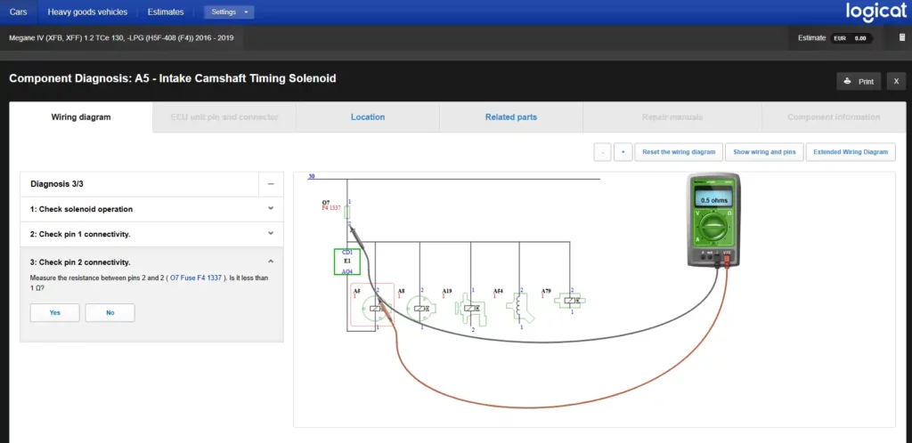
Step 3: VVT Actuator Check Using HaynesPro SmartCASE
Thanks to the SmartCASE function, HaynesPro reveals that this engine is known for common failures due to sticking VVT actuators. The system recommends:
Checking the control signal to the camshaft phaser solenoid
Verifying engine oil pressure
Testing continuity of wiring to the ECU
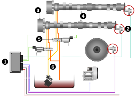
The interactive wiring diagram shows the exact location of the camshaft sensor, actuator, and relevant connectors.
Want to try SmartCASE and HaynesPro’s wiring diagrams?
Enjoy 7 days of free trial, no commitment, and experience the full power of the diagnostic tool.
👉 Request my free trial
Step 4: Live OBD Analysis and Target Values
Using the HaynesPro OBD gateway, the technician compares real camshaft angle values to the manufacturer’s targets.
📈 Result: A +12° advance at low RPM confirms uncontrolled VVT activity—pointing to either actuator sticking or incorrect timing.
Conclusion: Faster, More Reliable Diagnosis
With HaynesPro, the garage was able to:
Verify mechanical timing without unnecessary disassembly
Identify a known issue flagged by the manufacturer
Locate and test the actuator quickly
Offer a clear and accurate repair to the customer
✅ Time saved: +50%
✅ Fewer unnecessary part replacements
✅ Lower customer return rate
Ready to equip your workshop with HaynesPro?
Check out our flexible plans tailored for repair professionals.