
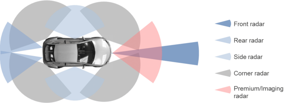
ADAS radar sensors play a crucial role in the operation of modern driver assistance systems: adaptive cruise control (ACC), autonomous emergency braking (AEB), collision warning, blind-spot monitoring, and more. Incorrect alignment or calibration can result in false alerts, loss of functionality, or compromised safety.
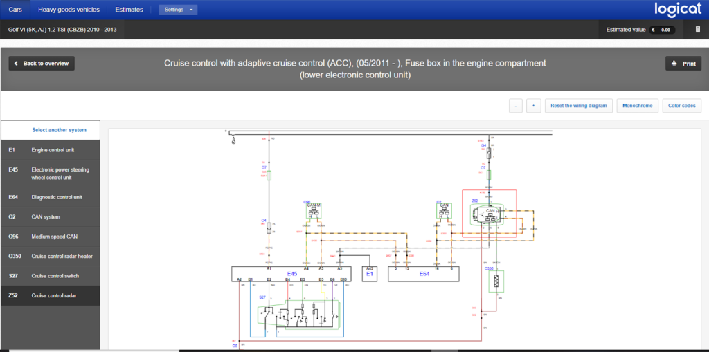
With HaynesPro, technicians have access to manufacturer procedures, guided calibration steps, and technical diagrams that enable them to quickly diagnose radar failures and perform precise alignment.
Symptoms of a Misaligned or Faulty ADAS Radar
Common signs encountered in workshops include:
- ADAS warnings on the dashboard: ACC unavailable, AEB deactivated, collision system offline.
- Frequent radar fault codes: C1A67, C1A69, B2A28, B2A2F, U0235 (manufacturer dependent).
- Erratic ACC behavior: sudden acceleration or braking.
- Collision alert too sensitive or inactive.
- Inconsistent vehicle detection: lateral offset, reduced range.
- After front-end impact or bodywork repair: radar misalignment.
Even a slight misalignment of a few millimeters is enough to disrupt driver assistance systems.
Step 1: Data Collection with HaynesPro
HaynesPro provides quick access to all information needed to diagnose and calibrate ADAS radars:
Radar module diagrams
- Mounting positions, adjustment screws, aiming angles, and attachment points.
Manufacturer calibration procedures
- Static and dynamic calibration.
- Exact distances between radar, calibration target, and vehicle center.
- Target height and angle.
- Environmental conditions (level ground, clear space in front, lighting).
Reference data
- Vertical and horizontal alignment values.
- Nominal radar range.
- ACC/AEB module parameters.
Guided HaynesPro tests
- Radar activation.
- ADAS function reset after repair.
- Live data monitoring.
These resources allow the technician to determine if the radar is misaligned, obstructed, damaged, or if the issue originates from the ADAS control unit.
Step 2: Expert ADAS Radar Diagnosis
1. Physical inspection of the radar
- Check mounting bracket alignment.
- Inspect bumper for deformations.
- Examine radar cover (logo or plastic panel): cracks, thick paint, moisture.
- Inspect connectors and wiring harness.
2. Static radar alignment
Using HaynesPro data:
- Position the vehicle on perfectly level ground.
- Install the calibration target at manufacturer-specified distance (e.g., 1.5–4 m depending on the model).
- Adjust horizontal and vertical angles using the adjustment screws.
- Check live data values: offset, aiming angle, detection distance.
3. Dynamic calibration
- Drive at the prescribed speed (often 40–90 km/h).
- Follow validation instructions via diagnostic tool.
- Verify radar beam stabilization.
4. Electronic diagnosis
- Read ADAS fault codes.
- Analyze real-time data:
- Target angle
- Signal strength
- Minimum/maximum detection distance
- Detected objects
5. Check for interfering conditions
Radar calibration may fail due to:
- Improperly positioned license plates
- Chrome elements or bull bars
- Modified wheels
- Lowered or raised vehicles
- Non-OEM bumpers
➡ HaynesPro procedures indicate incompatible areas and parts.
HaynesPro Case Study: Volkswagen Golf 7 – ACC Radar
Symptoms
- Dashboard message: “ACC unavailable”
- Fault code: C1103 – incorrect radar alignment
- No collision detected but bumper recently replaced
Diagnosis via HaynesPro
- Access to radar bracket diagram
- Static calibration procedure with manufacturer distances
- Nominal values:
- Horizontal angle: 0.00° ± 0.8°
- Vertical angle: 0.00° ± 1°
- Target distance: 1600 mm
Results
- Radar oriented 2° to the right (out of tolerance)
- Slightly bent bracket after bumper removal
- Calibration impossible until bracket is straightened
Solution
- Replace radar bracket
- Perform new static calibration + dynamic validation
- ACC/AEB functions restored
Time saved with HaynesPro: ~1 hour
By avoiding repeated calibrations and identifying the mechanical cause immediately.
Workshop Solutions
- Static or dynamic radar recalibration
- Replacement of radar bracket or module
- Horizontal/vertical angle adjustment
- Cleaning or replacing radar cover
- ADAS reset after repair
- ACC/AEB control unit software update
Tips for Technicians
- Always check the bumper or cover in front of the radar: even a thin layer of paint can disrupt the signal.
- Use HaynesPro to reference model-specific distances and angles.
- Perform dynamic calibration after static calibration if required by the manufacturer.
- For lowered or raised vehicles, recalibrate the radar.
- Document every step to reassure the client and avoid ADAS disputes.
Correct alignment and calibration of ADAS radars are essential to ensure the proper operation of modern driver assistance systems. HaynesPro provides technicians with precise diagrams, guided steps, and manufacturer values, saving time, improving diagnostic accuracy, and ensuring repairs meet safety standards.
A properly calibrated radar guarantees the reliability of ACC, AEB, and collision systems, directly contributing to driver safety.