

Hybrid vehicles combine power electronics, mechanics, and energy management strategies. For technicians and automotive bloggers, understanding the distinct roles of MG1 and MG2, and knowing how to interpret OBD-II codes (especially the P0xxx range), is essential for both diagnostics and repair optimization.
This article explains the MG1/MG2 strategy, clarifies P0xxx codes, and then walks step-by-step through a practical case study based on HaynesPro data and procedures.
1) MG1 and MG2: Roles and Control Strategy
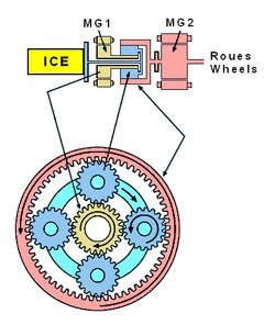
In the typical Hybrid Synergy Drive (HSD) architecture (e.g., Toyota), there are two motor-generators:
- MG1: Primarily used as a starter/generator, it starts the internal combustion engine, regulates engine speed, and can generate electricity to recharge the battery or power MG2.
- MG2: The main traction motor; it provides torque to the wheels in electric mode and recovers energy during braking (regeneration).
Power distribution and function change dynamically based on driving conditions (start-up, regeneration, engine assistance). Control is managed through power electronics (inverters, converters) and the hybrid powertrain control logic.
Why it matters for diagnostics:
Symptoms such as reduced electric assistance, loss of acceleration, or warning lights along with DTCs linked to the inverter, converter, or battery require technicians to determine whether the fault lies in MG1, MG2, the power electronics, or the HV battery pack.
2) P0xxx Codes – What Do They Mean?
OBD-II codes start with a letter followed by four digits.
For the powertrain, the P0xxx codes are generic (standardized by the OBD-II protocol), while P1xxx codes are typically manufacturer-specific.
In practice, a P0xxx code signals a powertrain/emissions-related fault that follows a universal format allowing for multi-brand diagnostics using standard OBD-II tools.
Common hybrid examples include:
- P0A80 – “Replace Hybrid Battery Pack”
- P0A7F – “Hybrid Battery Deterioration”
These codes often indicate HV module degradation, poor pack balancing, or faults in pack-voltage sensing circuits.
3) Diagnostic Methodology (Tools + HaynesPro)
Recommended Tools
- OBD-II scan tool capable of reading hybrid-specific and enhanced DTCs (e.g., Toyota Techstream, professional workshop tools).
- Multimeter / high-voltage clamp meter (HV safety procedures mandatory).
- Service manuals and wiring diagrams (HaynesPro, OEM data, TSBs).
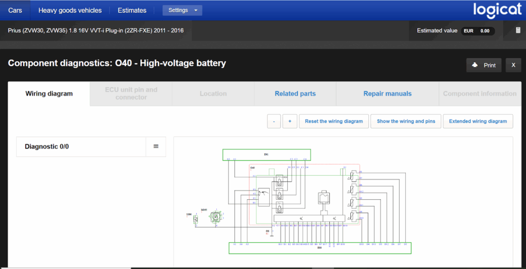
Role of HaynesPro
HaynesPro provides wiring diagrams, repair procedures, component locations, test values, and fault-handling workflows all crucial for accurately diagnosing hybrid systems (especially HV procedures and module testing).
Using HaynesPro helps reduce diagnostic errors, ensures tests are performed in the recommended order, and prevents unnecessary and costly component replacements.
4) Case Study
Context
Hybrid vehicle (Toyota Prius Gen 2/3 example). Hybrid battery and engine warning lights on, code P0A80 logged.
(Note: Educational case study based on typical HaynesPro data such as wiring diagrams, DTC procedures, and HV steps. Actual procedures vary by model.)
Steps Followed (HaynesPro Workflow)
1. Information Gathering
- Retrieve DTCs: P0A80 + possible secondary codes (P30xx/P3xxx).
- Verify reported symptoms (start-up issues, power loss, hybrid/EV mode behaviour).
2. HaynesPro Consultation
- Access HV schematic, battery module locations, pinouts, and HV isolation procedures.
- Retrieve reference values (module voltages, resistances, test steps using diagnostic tool)
3. HV Safety & Zero-Voltage Procedure
- Isolate the HV pack (service plug, 12 V disconnection if required).
- Follow HaynesPro safety checklist and OEM safety protocols.
4. Electrical Checks
- Measure total pack voltage and individual module voltages.
- Check continuity of busbars and connectors (look for corrosion or hot spots).
5. Module Analysis
- If voltage or resistance deviations are found between modules, HaynesPro provides acceptable ranges and test methods (load/discharge tests or ECU-based diagnostics).
6. Differential Diagnosis
- If modules test OK: check BMS/smart unit, sense wires, and inverter (MG1/MG2).
HaynesPro supplies expected test points and signal values.
7. Decision
- If several modules are outside tolerance → replace or refurbish the pack.
- Otherwise, repair connectors/smart unit or recalibrate the BMS.
8. Validation
- Clear codes, perform a test cycle (charge/discharge, road test), and verify no new DTCs appear.
Result:
Following HaynesPro-guided measurements, the workshop identified two modules with high internal resistance (imbalance).
After module replacement/reconditioning per HaynesPro procedure → codes cleared, system restored, and regenerative capacity recovered.
(Note: This is an illustrative example; real diagnostics may lead to full pack replacement depending on damage extent.)
5) Workshop Checklist MG1/MG2 et P0xxx-Oriented Hybrid Diagnostics
- Read and record DTCs + freeze-frame data.
- Distinguish generic P0xxx codes from manufacturer-specific P1xxx codes.
- Consult HaynesPro for HV schematics, locations, and DTC procedures.
- Perform HV isolation and safety checks before any intervention.
- Measure pack and module voltages (compare with HaynesPro reference values).
- Test inverter/MG1/MG2 outputs if necessary (phase signal analysis).
- Document repairs and test traces for customer reporting.
Optimize your diagnostics with HaynesPro: faster and more reliable. Your clients and your workshop will notice the difference in every service.
Request your free HaynesPro trial today!